 Hello and welcome to the CAD Cafe. Unless you live high up in the mountains or right next to the sea, it's HOT where you are! So get yourself an iced drink - if your IT guy lets you have liquids near the computer - relax and try something new from AutoCAD 2008.
Today we're going to make a custom Multileader.
In case you aren't familiar with that phrase, let me explain. It's simply an arrow pointing at something you want people to notice, with a number that corresponds to a keynote, usually with a shape around it like a rectangle or a circle. There are a lot of them that come with AutoCAD, but maybe you want to use the same one you've always used. It's part of your company's signature drawing style! Still, wouldn't it be great to have the functionality offered with 2008 multileaders? You can!
 This first illustration shows the different types of multileaders that are included with AutoCAD. I created a few different styles to show that you can use any arrowhead, line/spline, and shape combination you like. The process for creating these styles is exactly the same as for a custom Multileader, just choose one of the shapes from the block list.
 First step: create a block if you don't already have a custom one. Draw your keynote & insert an attribute at the size you want your keynote to print out in 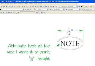 paperspace. I used this ellipse at the size you see dimensioned here.
 paperspace. I used this ellipse at the size you see dimensioned here.
 Important Note! Don't use an annotative text style for your attribute!
Another thing you might want to consider is creating all this in a template file you always use, so once you've gone to the trouble of creating it, the style is available to you.
Another thing you might want to consider is creating all this in a template file you always use, so once you've gone to the trouble of creating it, the style is available to you.
Next, make your block but make sure it's NOT annotative. All the annotation happens in the Multileader style.
You'll want to make sure to Save at this point. AutoCAD won't put your block in the list if you haven't saved the drawing. Plus who wants to make the block over again just because they forgot to save?
Second step, use the button in your Dashboard to start the Multileader Styler command.
Second step, use the button in your Dashboard to start the Multileader Styler command.
 This is a lot like creating a dimension style, you choose options from each tab.
 Reading from left to right; under the Leader format tab you choose either lines or splines, line color, linetype, lineweight, also arrowhead style & size. Next is Leader Structure where you can specify how many points your line will have, as well as a specific line angle if you need that. Here you'll choose how it's scaled - annotative or not, same as with dimension styles. As you choose things you'll see the preview of your multileader change.

The last tab, Content, is where you choose your own block.

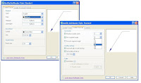
Here is illustrated all the choices you have when you create your own Text Multileader Style. I was going to explain it all, but in this case a picture is definitely worth a thousand words, and those of you who aren't interested in this can just skip this picture, and you won't have to read a thousand more words!
Below is the Content tab with 'Block' chosen; you

can see all the choices that come with AutoCAD.
I clicked where you see the words "User block" highlighted, then a list of all the blocks in the drawing popped up and I chose my 'Custom Keynote' block.
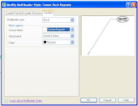 Here you can see my preview, I chose my custom block, straight lines, annotative scale and all colors by layer.
 Here you can see my preview, I chose my custom block, straight lines, annotative scale and all colors by layer.
Remember, if you want your Multileader to be Annotative, you make it annotative here in the Style Manager, on the Leader Structure tab, under 'Scale'. You don't use an annotative block, it won't work.
Guess who tried it? Right in one! So when I tell you it won't work, you can believe me.
 Here are my custom Multileaders, inserted through the viewport and all scaled perfectly. I added more leaders to one of them to demonstrate that a custom block multileader style has all the functionality of the ones that come with AutoCAD.
I couldn't resist changing the layer colors per viewport, just so the electrical would stand out more in that second viewport. While in Paperspace, I clicked inside that viewport, opened the Layers Manager and changed the colors in the "VP Color" column. Here's a picture so you could see which ones I changed and how they're highlighted when you do change them.

I hope this was helpful - you can use the new Multileader functionality in 2008 and you don't have to give up any custom keynote blocks you're already using.
Keep cool until next time!


