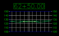
 Here's a question for you, do you use the "View/Edit Corridor Section" command? Well, if you don't, you should. It's a great way to see what's going on at each section of your corridor and gives you the ability to edit each individual section. If you do use it, you may have noticed one of it's limitations. It will only display information for you to the limits of the corridor. For example, you have an assembly that daylights to the existing ground on both sides. Now, the View/Edit Corridor Sections, will only display information up to daylight point. If you want to see more, you could always create a sample line and a section for that station. However, that only works for one of them and creating views for every section sometimes is a waste of time plus, it doesn't help much when you are actually editing the section.
Here's a work around I thought of today. Basically, you simply add data to your assembly out to the area you want displayed.
Here's the method. As you can see in the first picture, I have a section that displays nothing beyond the daylight connection.

Now, what I want to do is see what the section looks like beyond the tie in points. The trick I use is to add another subassembly to my assembly. This subassembly will extend out a desired distance and the section will display out to the new subassemblies limits. The subassembly I've chosen is LinkOffsetAndSlope. I use an offset distance of 75' for one of them and -75' for the other (offset has no side so negative is left) and a 0% slope. Now, I simly add this to my assembly and I end up with this.

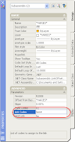
One thing you may notice is those purple (or other colored) lines. The way we get rid of them is to change them in the code set. The first thing we do is assign a specific link to them, I called mine "None" but you can call it whatever you want. This is a property of the subassemblies and can be accessed various ways, I like the properties dialog box personally.

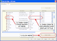
Now we need to add this information into our Code Set Style. Right click on the code set you are using and select edit (code sets are found on the Settings tab of the Tool Space under General->Multipurpose Styles->Code Set Syles). On the Codes tab of the dialog box, down in the lower right corner, there is a button that allows you to import the codes from corridors, assemblies, and subassemblies. Click on this, select your corridor, assembly, or subassembly (doesn't really matter) and the None link code is added to your code set. Now, simply create a link style that doesn't display anything and assign it to your link. Make sure you have your 3D display set to not display anything either.

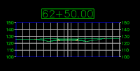
This is now what your View/Edit Corridor Sections will now look like:

You'll probably want to erase these subassemblies out of your corridor when it comes time to plot your sections.


3 comments:
Isn't it easier to set up a section view style that extends the the left and right?
Then you always have it, as wide as you want, without having to add these extra links.
You can set that section view style as to be used by default when viewing/editing sections in the corridor command settings.
Brian,
Nice one.
You can also change your Edit/View corridor section style and specify the number of grids to the left and right of the graph.
A lot simpler than your approach.
Regards,
Harold
Yep, you are both correct. That would be a much easier method. When I was first pondering this issue, I didn't think it would actually sample the existing ground in the padded areas but it does.
Brian
Post a Comment