Thursday, October 25, 2007

Hidden Files


Hello everyone, this short note was inspired by my annoyance at drilling through my computer's files looking for just that one folder.
As you know, AutoCAD for some time has put their template and other files in a deep dark convoluted path of file folders. They had to do this, I've been told, for AutoCAD to play well with Windows. For those of you who don't have an IT or CAD Manager rearranging things, I'm sharing my list of the Hidden Files that I frequently access. I just got sick of trying to remember which ones are in Local Settings, and which one is in All Users, so I copied them all onto a document, and I'm sharing it with everyone else who doesn't have the time to memorize long file paths.

Obviously, you would substitute your User name for mine, unless you too are named luann. Once you get to the Autodesk folder, whatever version of Autodesk products you have installed has its own folder, so you would substitute that name where I have "AutoCAD2008".

Templates
C:\Documents and Settings\luann\Local Settings\Application Data\Autodesk\AutoCAD 2008\R17.1\enu\Template

Tool Palettes
C:\Documents and Settings\luann\Application Data\Autodesk\AutoCAD 2008\R17.1\enu\Support\ToolPalette

CTB & STB Files
C:\Documents and Settings\luann\Application Data\Autodesk\AutoCAD 2008\R17.1\enu\Plot Styles

Plotter PC3 files
C:\Documents and Settings\luann\Application Data\Autodesk\AutoCAD 2008\R17.1\enu\Plotters

CUI Files
C:\Documents and Settings\luann\Application Data\Autodesk\AutoCAD 2008\R17.1\enu\Support

Custom icons
C:\Documents and Settings\luann\Application Data\Autodesk\AutoCAD 2008\R17.1\enu\Support\Icons

Textures & bitmap bump files
C:\Documents and Settings\All Users\Application Data\Autodesk\AutoCAD 2008\R17.1\enu\Textures


Just a final note: These file locations are straight out of the box. I know you can set AutoCAD to look elsewhere, but since I do a lot of training, I need to leave things that way so I can show new users where things will be on their computers.

I hope at least one person out there finds this useful. If so, my work here is done.

Wednesday, October 17, 2007

Editing Blocks in AutoCAD & AutoCAD LT

Hi everyone! Yes, I got my hair cut, this is the picture of it that I hate the least- I inserted it here only in case I meet anyone who reads this. Love the haircut, hate photos. But doesn't everybody hate pictures of themselves?

While demonstrating for a client the differences between AutoCAD and AutoCAD LT, I came across one that has nothing to do with 3D. Changing blocks is something everyone has to do at some point, and since AutoCAD LT doesn't have the same cool "Edit-block-in-place" toolbar that full AutoCAD does, I wanted to show you a work-around for it.

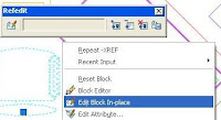
First of all, with full AutoCAD: to change an existing block in your drawing open up the Refedit tool bar. I know that name isn't necessarily going to stick in your brain, so another way to get to it is to select any block, right-click and choose "edit block in place". This will open up the Refedit toolbar. If you don't dock it, it will close as soon as you finish this command, so dock it if you're going to edit more than one block.
In this screen capture on the right I've got both ways showing.


Here is Drawing A, a typical office, with blocks used for everything. Let's say in full AutoCAD you want to change the chair block. When you start the REFEDIT command, every instance of the block except the one you chose all disappear, and the rest of the objects in the drawing are grayed out. One nice thing about editing a block this way compared to exploding it and resaving it with the same name is that it doesn't matter if the block you edit is rotated, it won't mess up the other instances of that block.
Once you've changed the block the way you want, click the 'save changes' button, the one on the right side of the toolbar. If you've lost the toolbar don't panic! Just type in REFCLOSE and you'll have the option of saving your changes.
Every instance of that chair now changed.


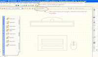
But in AutoCAD LT, there is no REFEDIT command. So a way around this is to use the same editor that was designed to create Dynamic Blocks. Select your block and then click the Block Editor Button, it looks like a lightning bolt. It's on the standard toolbar and also on the Tools Menu Pulldown (I circled it in the picture below). In that editor you can simply change the block, you're not obligated to add dynamic features to it.

In Drawing B, in LT, I opened the computer block in the Dynamic Block Editor, erased the screen & drew a flat screen in its place, and changed the mouse to an oval.

When you're in the Block Editor, you don't get the fading effect as in full AutoCAD, but when you exit the block editor and save the changes, each block insertion will change. And that, after all, is the object of this exercise.

I wanted to mention that if you get blocks from sources that don't name things the way you would like them, there is an easy way to fix them. In the Format pulldown menu, the very last thing is Rename, or you can type in RENAME, or the shortcut REN. Once the command starts up you choose which type of object you want to change, (for example blocks, layers, text styles, etc.) and then choose the individual one to rename, and fill in the box.
I mention this here because I edited the chair block in Drawing A - opened with full AutoCAD - and the computer block in Drawing B - opened in LT - so I could show you the following tip. I renamed the computer block in Drawing B in order to insert it into Drawing A without redefining A's existing computer block.

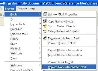
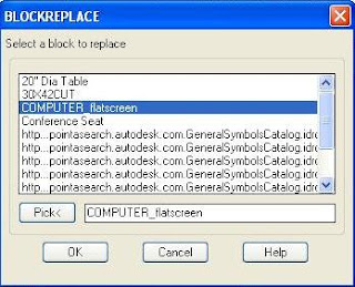
Here's one more helpful tip about changing blocks in full AutoCAD. (Sorry but Express Tools are not available in LT) Say you get a drawing from someone that you need to use for the basis of your design, but the symbols they use are all different than your company standards. There is an Express Tool that will help you, in the Express pulldown menu > Blocks > Replace block with another block. You could insert your symbol blocks into the drawing, and then use this to instantly replace theirs with yours. In this case I copied & pasted my newly named computer block into the original drawing. Then I started the REPLACEBLOCK command.

You can choose the one you want to replace from the list of blocks in your drawing, or use the 'Pick' button to choose it right from your drawing. This is really helpful for those times you get a drawing from someone and they've named every block using their catalog number!
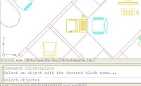
This picture is what you see as soon as you click on that 'Pick' button. I'm picking the block I want to change, the original computer block, and it will immediately bring me back to the dialog box to choose the replacement block, shown in the next illustration.

Again, I can choose from the list or use the pick button. I found mine in the list in the following illustration.

The final thing this command will ask you is if you want to purge the old block out of your drawing or not.

One thing you want to be sure of when you replace one block with another is that they're drawn at the same scale and rotation.


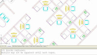
As the last picture shows, all the old computers with big fat monitors have been exchanged for the nice new ones with flat screens. If only it were that easy in real life!
And just to re-emphasize, due to a comment I had, this work-around using the Dynamic Block editor is not a good way to edit blocks in Full AutoCAD. For that, use REFEDIT. This is just a work-around for people who have AutoCAD LT and want to edit blocks without exploding them.
I'll be seeing some of you hopefully next week. Comm-Tech is doing a demonstration of the new features of AutoCAD 2008 and Civil 3D 2008 in Grand Junction and Vail on Friday, the 26th of October. Please tell me if you've enjoyed reading any of my blogs, it would be great to meet you!

Tuesday, September 18, 2007

New Training Center

Hi everyone! I'm departing from my normal subjects to show you a little of the project the owners of our company have been working on all summer. As any of you who've come to Comm-Tech for training know, for about two years now our main office has been in Frederick, Colorado. It's a nice town, but everything was at least 5 miles away. It took a long time to go out to lunch, and if you wanted to run some errands during the lunch hour - well, forget it, you couldn't. We were on the frontage road of I-25 between Highways 52 and 119. But now we've moved to Boulder!

On the above map from Google I marked the two locations.

Here's a few pictures of the progress of our new building. It is so nice!


This is one of the future classroom, taken as I was standing in the front where I would normally stand. We'll have our coffee and snacks on that countertop.


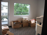
On the right is my future office - notice the window? I took those 2 photos on September 3rd. When you visit us you'll see the huge progress we've made!
These next 2 were taken while we were in the moving process. What a huge job that was! One is the open office area, the other is looking at the balconey through the boss's office door.


We moved into the building on September 8th. We worked our heads off, but there was still an awful lot of work to do.

The photo of them hanging the screen for the projector looks a little surreal, doesn't it?

Here's the new kitchen, we'll have plenty of space for you all to eat your lunches there during class. Within walking distance is a PDQ station with a Subway inside, and across the street is a hotel (for out-of-town students) with a wonderful restaurant inside, the Eggcredible Cafe.


These trees are what you see outside the kitchen window. Makes a nice change from gazing at the semi trucks on I-25.
Today I took this picture of the classroom they've named Cherryvale Trail - it's all finished. Most of the time the AutoCAD classes will be in this room, and the Civil 3D, Map and Land Desktop classes wil be in the other one, named Mapleton Hill. Everything is set up and ready to go!

Below is the view of our building looking west on South Boulder Road. I realize when you're driving here you won't quite see this view, since you'd have to be in the wrong lane. But I wanted you all to notice at the bottom of the photo is an entrance to some of Boulder's hiking trails. I got this map that shows this entrance and some of the nearby trails from the City of Boulder's website.


On the right is a picture of the new building taken from the corner of South Boulder Road and Manhattan Circle, looking east.

Today was a beautiful day, so I climbed up onto the roof parapet and took this photo of the Flatirons. We all love looking at the mountains. We're sure you'll love our new training center, with it's bigger classrooms, better kitchen, and its more convenient & attractive location. I sincerely hope you come to the Open House on Friday the 21st!

Monday, September 17, 2007

New Dimension Tricks

We are completely moved into our newly remodeled office building. (I'm posting a bunch of pictures in my next blog.) After so much chaos and disruption I am very happy to get back to a normal work day! If you click on the link you can see our new digs. I now have a window looking out over trees and things! Who wouldn't love that?

Today I'm going to show you a couple new features that have been added to Dimensioning.
Here's a picture of the two I'm writing about, shown on the pulldown menu, Dimension Space & Dimension Break. Of course these are on the Dashboard and the Dimension Toolbar, I just like the fact that you can see the icon and the command name at the same time on the pulldowns.


This first tip is a little different take on the Dimension Space (DIMSPACE) command.

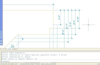
When you have a line of dimensions that maybe should have been created with "DIMCONTINUE" - as you see on the right here - with Dimension Space you can easily fix 'em up. After starting the command, choose the dimension you want all the others to line up with. The one I chose is highlighted there (on the right)

Then use a crossing window to pick all the ones you want to line up with it, and use Zero as the spacing.


All the dimensions will line up with the one you chose as a reference. Sweeeet.


This command is most often used when you have a whole bunch of dimensions stacked too closely, or just so unevenly that they don't look professional.
The steps are the same - start the command, pick the reference dimension, and then use a crossing to pick the rest of the dimensions you need to line up properly.


Then enter the spacing distance in drawing units. In this case the spacing chosen was 15. Looks a lot better, doesn't it?


Remember, if the number you chose just doesn't look right, there's always Undo!


The last thing I want to show you today is the Dimension Break command.

When you have dimensions that overlap you don't have to use a Wipeout anymore. You can set any dimension to break where it overlaps another one by using the DIMBREAK command. It's really easy to use.

Start the command, either select the object you want to break, or M for Multiple and then select several dimensions using a crossing.

Then you have to hit Enter to accept the 'Break' option, and that's IT.


Nicest of all, when you grip edit the location of a dimension that has had DIMBREAK applied to it, the break moves with it.

Give this a try! I'll be writing again soon, so have fun drawing and I'll see you here next time.

Wednesday, August 22, 2007

Customize the Dashboard

Hi again! This time let's look at how to customize the Dashboard.

I know it's hard to change the way you've always accessed your commands, so I thought perhaps if you knew you could customize the Dashboard to look the way you want it, you all might just give it a try.
First of all, so we're all on the same page - the Dashboard was there in AutoCAD 2007, but only in the 3D Workspace.
Now in 2008 they've added it to the Workspace named '2D Drafting and Annotation'. They've also added a lot of functionality; you can customize your Dashboard now like you could the toolbars, and since they hide themselves when you don't need them, you can maximize your drawing space. (I mean it doesn't have to be all filled up with toolbars any more.)

Each of those rows with the faint grey line underneath is a control panel. You can control which control panels show. Right click on any control panel, you'll see the list of available panels. Only the ones that are checked will show. So, the first way you can customize the user interface is by choosing which control panels you would use. Once you have that set up, go to the Workspace Toolbar ( or the Tools menu; Tools>Workspaces ) and save as a new name. Next time you want just those Control Panels, choose that Workspace from your list and voila, you've got it. ("Tish, you spoke French!")

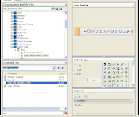
The fun part is making your own control panels. You can right click on any of the panels (not anywhere else on the Dashboard) and select "Customize". It'll put you into a folded-up display of the CUI dialog box. ( Customize User Interface). In the illustration here I've labeled where you click to open up the dialog box.

To open up the list of exising Dashboard panels, in the top left section of the CUI dilaog box, where it says "Customization in all CUI files" click the "+" in front of "Dashboard Panels". Right click exactly on those words and one of your choices will be "New". I selected that, in this picture you'll see my new panel.
One way to add commands to my panel is to find them from the list on the bottom there, and just drag them one at a time onto the Control Panel. If I wanted to, for example, I could drag every different Arc command onto one Control Panel and have them all at my fingertips.

By right-clicking on your Control Panel, you can add another row, a separator or a flyout; duplicate an object, or remove it.
Another, faster way to make Control Panels is to drag an entire toolbar onto a Control Panel. Up in the top section, find a toolbar that has most of the commands you want, and just drag and drop it onto your Control Panel. You need to drag it right onto the name , it will make a flyout on the row if you drag it there. The tool palette turns into a row on your Panel


Now on the right side of this dialog box you can see a preview of your new Control Panel. Notice the toolbar you dragged down formed a row, and the original row is now moved and became the 2nd row. By right-clicking on it, you can delete the other row if you don't need it.

Also, by right-clicking on individual buttons, you can delete any you don't want.
The fun part is adding new commands to these. Any command that you can find in the bottom left section of the CUI box can be dragged onto any dashboard. In the next illustration, I dragged a command from Express Tools that doesn't have an icon assigned to it. Notice the question mark for a button.
Also notice in the lower right corner, all the icons used for Toolbars and menus are showing there. It's not hard to customize one of those to make your own icon.


Scroll through the icons until you find one that's close to what you would like for your command. For the following example, I dragged the command for snapping Midway between two points onto my toolbar, so I started with the icon for Osnap-midpoint. In the picture below you can see it in the background, I clicked on Edit and then changed the bitmap as you see here. Then I just pick the "saveas" button, and AutoCAD puts me into one of those deeply buried folders, named Icon. Use that to store your custom icons.


Once you've saved it, the icon shows in your list, so all you have to do is scroll down to the bottom of the list and select it. Then it'll show up on your Control Panel.
By the way, if you don't use the botton now, it won't show up here later easily. It's best to do these one at a time.


Here is another custom button I made, for the Express Tools command "Replace block with another block". In this illustraton you can see the path where my custom icons are saved by default. Using this default location makes it easy for you to transfer these next time you upgrade the software.


Last of all, if you want to assign an image to the Control Panel itself, it's as easy as pie. Click on the title of your dashboard, scroll through the icons and click one. It'll then be assigned to the edge of your control panel. You don't have to do that of course. I made a custom one, and perhaps I shouldn't have used red, since all the other icons are just shades of blue. What can I say ? - I like a lot of color!

Tuesday, August 21, 2007

Vault server on a 64 bit OS. No problem, right?

So this last week, I went to a customers site to install Vault on their server for them. No problem, I've done this a lot of times. I get to their office and I notice their server is running Windows Server 2003 x64. Uh oh. 64 bit software. I haven't dealt with it yet and I know Civil 3D doesn't run on it. So, off to the Autodesk website to make sure it's supported http://usa.autodesk.com/adsk/servlet/index?siteID=123112&id=8915326. Alright! It's supported for the vault server! Away I go. I pull out the disk, throw it in the machine, and up pops a warning. I don't remember the exact wording but it said something along the lines of:

Hey! You can't do that! Civil 3D isn't supported on a 64 bit OS! I'm cancelling the installation setup!

I know, I should have taken a screen shot of the message, but you get the point. So, I can't run the setup.exe for Civil 3D. No problem, there's probably another exe file for the vault just like there was in 2007. I browse through the install disk and find the vault msi file (that's the installer file). I double click on it hoping it will install the vault server and I get another nasty gram (again, I should have taken a screen shot):

Hey! You can't do that! Vault Server has to be installed through the setup.exe file!

Wait a minute, I can't run the setup file because this is a 64 bit OS but I have to run the setup file to install vault, which is supported on a 64 bit OS. Sounds like the left hand wasn't aware of what the right hand was doing.

Now, if you find yourself in this situation, there are a couple things to do. If you are on subscription, you can download the vault install files from the subscription center. I wasn't aware of that option so I didn't do that. The other option is to contact Autodesk Tech Support. They can e-mail you an alternative Civil 3D msi and ini file. Simply copy the install disk to a local drive, replace the two files, and away you go. You can also contact your reseller for assistance with this (if you don't have a good reseller, you can always check out CommTech www.ctcivil.com).

Wednesday, August 1, 2007

Civil 3D and Land Deskotp 2008 Service Packs

For those of you that don't live and breath Civil 3D like I do, you may not be aware that there an now service packs available for both Civil 3D 2008 and Land Desktop 2008. Ok, big deal. So why Blog about them? Well, you have to make sure you get the right one or it won't work for you. Remember, there are two different versions of LDT 2008.

First, the easy stuff. The Civil 3D service pack can be downloaded from the Autodesk website. Simply click here:
http://usa.autodesk.com/adsk/servlet/ps/dl/item?siteID=123112&id=9909730&linkID=9240698. There is only one version of the service pack so download it and install it.

Now the tricky part, Land Desktop. For those of you that have licenses of Civil 3D, even if you aren't using Civil 3D will most likely have the Civil 3D Land Desktop Companion. If that's you, then you'll need to download your service pack here:
http://usa.autodesk.com/adsk/servlet/ps/dl/item?siteID=123112&id=9909673&linkID=9240698.

If you don't have Civil 3D, you probably have Land Desktop and you can download your servivce pack here:
http://usa.autodesk.com/adsk/servlet/ps/dl/item?siteID=123112&id=9909659&linkID=9240778.

Let's all hope this service pack will fix all those little bugs!


Tuesday, July 17, 2007

Custom Multileader Style

Hello and welcome to the CAD Cafe. Unless you live high up in the mountains or right next to the sea, it's HOT where you are! So get yourself an iced drink - if your IT guy lets you have liquids near the computer - relax and try something new from AutoCAD 2008.
Today we're going to make a custom Multileader.

In case you aren't familiar with that phrase, let me explain. It's simply an arrow pointing at something you want people to notice, with a number that corresponds to a keynote, usually with a shape around it like a rectangle or a circle. There are a lot of them that come with AutoCAD, but maybe you want to use the same one you've always used. It's part of your company's signature drawing style! Still, wouldn't it be great to have the functionality offered with 2008 multileaders? You can!
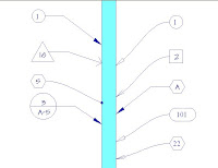
This first illustration shows the different types of multileaders that are included with AutoCAD. I created a few different styles to show that you can use any arrowhead, line/spline, and shape combination you like. The process for creating these styles is exactly the same as for a custom Multileader, just choose one of the shapes from the block list.


First step: create a block if you don't already have a custom one. Draw your keynote & insert an attribute at the size you want your keynote to print out in paperspace. I used this ellipse at the size you see dimensioned here.
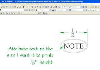

Important Note! Don't use an annotative text style for your attribute!
Another thing you might want to consider is creating all this in a template file you always use, so once you've gone to the trouble of creating it, the style is available to you.

Next, make your block but make sure it's NOT annotative. All the annotation happens in the Multileader style.
You'll want to make sure to Save at this point. AutoCAD won't put your block in the list if you haven't saved the drawing. Plus who wants to make the block over again just because they forgot to save?
Second step, use the button in your Dashboard to start the Multileader Styler command.
This is a lot like creating a dimension style, you choose options from each tab.


Reading from left to right; under the Leader format tab you choose either lines or splines, line color, linetype, lineweight, also arrowhead style & size. Next is Leader Structure where you can specify how many points your line will have, as well as a specific line angle if you need that. Here you'll choose how it's scaled - annotative or not, same as with dimension styles. As you choose things you'll see the preview of your multileader change.
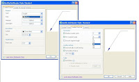
The last tab, Content, is where you choose your own block.
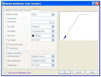

Here is illustrated all the choices you have when you create your own Text Multileader Style. I was going to explain it all, but in this case a picture is definitely worth a thousand words, and those of you who aren't interested in this can just skip this picture, and you won't have to read a thousand more words!

Below is the Content tab with 'Block' chosen; you
can see all the choices that come with AutoCAD.
I clicked where you see the words "User block" highlighted, then a list of all the blocks in the drawing popped up and I chose my 'Custom Keynote' block.
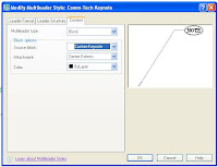
Here you can see my preview, I chose my custom block, straight lines, annotative scale and all colors by layer.
Remember, if you want your Multileader to be Annotative, you make it annotative here in the Style Manager, on the Leader Structure tab, under 'Scale'. You don't use an annotative block, it won't work.
Guess who tried it? Right in one! So when I tell you it won't work, you can believe me.
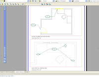
Here are my custom Multileaders, inserted through the viewport and all scaled perfectly. I added more leaders to one of them to demonstrate that a custom block multileader style has all the functionality of the ones that come with AutoCAD.


I couldn't resist changing the layer colors per viewport, just so the electrical would stand out more in that second viewport. While in Paperspace, I clicked inside that viewport, opened the Layers Manager and changed the colors in the "VP Color" column. Here's a picture so you could see which ones I changed and how they're highlighted when you do change them.


I hope this was helpful - you can use the new Multileader functionality in 2008 and you don't have to give up any custom keynote blocks you're already using.
Keep cool until next time!