 Hello and welcome to the new CommTech Cad Cafe!
 Since you've already met Brian, allow me to introduce myself. My name is LuAnn, and I have been working with AutoCAD since release 10, and giving instruction in it for 6 years. I'll be posting tips and instructions for all of you who use regular vanilla AutoCAD. Most of us only use the commands and tools we already know, hopefully I can show you some things you might never have tried that will speed up your work. I also will be posting things geared towards beginners, since I meet so many of you in our classes.
 I'm going to start out with creating a custom Tool Palette, then adding command tools to it. Tool Palettes are not just for inserting Blocks!
 I'm going to start out with creating a custom Tool Palette, then adding command tools to it. Tool Palettes are not just for inserting Blocks!
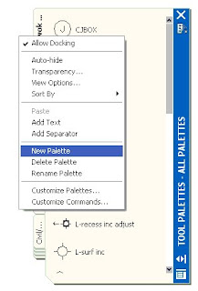
Tool palettes are the easiest way to customize your AutoCAD experience, and you won’t have to worry about ruining anything in your system! To make a new tool palette, right click on the spine of the tool palette, or in the gray area of any palette, and choose “New Palette”. Immediately a new palette comes up, with the cursor blinking in a window, waiting for you to type in a name. It's already highlighted, so just go ahead and type in a name for your palette. (You can easily rename a palette, notice that "Rename Palette" is one of your right-clicking options)
One easy way to add drawing commands to a tool palette is to drag an object, like a line or a circle, onto your tool palette. The secret to this is to click the object so you see the grips, and then put your cursor anywhere on the object except for a grip, and drag it onto your new tool palette. When this is working right, your cursor turns into an arrow, a copy of the object gets dragged along and you’ll see a small rectangle at the base of the arrow. 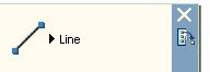
As soon as you see a black line on the palette, you can let go of the mouse button, and a fly-out button with the object you dragged on it will appear. One click on this button will start the same command; in this example I dragged a line onto the palette, so it’s showing a line.

As soon as you see a black line on the palette, you can let go of the mouse button, and a fly-out button with the object you dragged on it will appear. One click on this button will start the same command; in this example I dragged a line onto the palette, so it’s showing a line.
If you click on the flyout arrow, a small submenu will appear with buttons for LINE, ARC, CIRCLE, ELLIPSE, POLYLINE, RAY, SPLINE, and XLINE. Using any of those buttons will start that command, and the object will be drawn with the same properties (layer, color, linetype) as your original object.
If you right-click on the button that was created, you have the option there to rename it – for example, you could name it after the layer you’d be drawing on. Also in the right-click menu is the properties option, and here you can change your flyout a little bit.
 If you click on “Flyout Options”, an ellipsis button will show, (the one with “…” on it ) simply click on that to choose which of the above commands you want shown on your flyout. For example, if your button was created on layer ‘property lines’, you could uncheck the boxes for RAY, CIRCLE and ELLIPSE if you would never use those to draw your property lines.
 In this example , I have unchecked everything except LINE, ARC and POLYLINE. The next picture shows how this button will look.
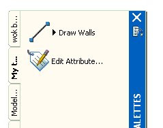
If you only want one command to show, click in the box labeled “Use flyout”, and you will get the ‘No’ option, which will eliminate the flyout and change your button into just one command. Make sure before you do this that the last command you used it for is the one you want; because that’s the one it will default to. Here I changed that option to "No" which changed this into just the line command. It's set on layer 'Walls', so I named it Draw Walls. This could really be helpful when you're training in a new person who always draws things on the wrong layer!
 Make sure before you do this that the last command you used it for is the one you want; because that’s the one it will default to. Here I changed that option to "No" which changed this into just the line command. It's set on layer 'Walls', so I named it Draw Walls. This could really be helpful when you're training in a new person who always draws things on the wrong layer!
 Another thing you can do to customize a tool palette is to put commands from various toolbars on it. If you get tired of opening a toolbar just to get to one command, and you work in a place where they don't want you messing around with the CUI file, this is the tip for you! First of all, open up the toolbar from which you want to use a button or two. Next, on the spine of the tool palette you are customizing, right click and in the menu find "Customize Tool Palettes". When you click on this, a big dialog box comes up. In a later post, I'll talk about some other things you can do here, but for now all you need to do is keep this box open.
Put your cursor on the button you want to use, and drag it over onto the tool palette. As soon as you see the black line shown in the next illustration, let go, and the command is copied onto your tool palette. In the illustration, I have a red arrow pointing to the command I am copying - you can see it's been pushed down, but my cursor won't show up on the screen capture. I am dragging that command onto my own custom tool palette, and the next illustration shows how it will look  when it's done.
 when it's done.
 This will not work with any buttons that have flyouts or menu pulldowns, like for example the Layers pulldown; the ones you can't copy will be greyed out as soon as you open the Customize Tool Palettes Dialog Box. When you've finished dragging buttons onto your tool palette, just close the dialog box.
Using this simple method, you can create as many custom tool palettes as you need. Tool palettes are not limited to Block insertion!
Using this simple method, you can create as many custom tool palettes as you need. Tool palettes are not limited to Block insertion!


