Showing posts with label Civil 3d. Show all posts

Wednesday, August 1, 2007

Civil 3D and Land Deskotp 2008 Service Packs

For those of you that don't live and breath Civil 3D like I do, you may not be aware that there an now service packs available for both Civil 3D 2008 and Land Desktop 2008. Ok, big deal. So why Blog about them? Well, you have to make sure you get the right one or it won't work for you. Remember, there are two different versions of LDT 2008.

First, the easy stuff. The Civil 3D service pack can be downloaded from the Autodesk website. Simply click here:
http://usa.autodesk.com/adsk/servlet/ps/dl/item?siteID=123112&id=9909730&linkID=9240698. There is only one version of the service pack so download it and install it.

Now the tricky part, Land Desktop. For those of you that have licenses of Civil 3D, even if you aren't using Civil 3D will most likely have the Civil 3D Land Desktop Companion. If that's you, then you'll need to download your service pack here:
http://usa.autodesk.com/adsk/servlet/ps/dl/item?siteID=123112&id=9909673&linkID=9240698.

If you don't have Civil 3D, you probably have Land Desktop and you can download your servivce pack here:
http://usa.autodesk.com/adsk/servlet/ps/dl/item?siteID=123112&id=9909659&linkID=9240778.

Let's all hope this service pack will fix all those little bugs!


Monday, July 16, 2007

Feature Line Labels

So, you have a feature line that you would like to label and you want to see the elevations of the verticies. Well, I've got good news for you. You can create a general line label style that can do that.

First thing you'll need to do is create a label style. The general line label styles are found on the Settings tab of your workspace -> General -> Label Styles -> Line. Right click on Line and select New...


Give your new label a name. In this example, I'm creating a label for the end of the line so it's called "End Elevation" (original, I know). On the layout tab, go ahead and remove all the components (select the component name and hit the red X) so we are starting with an empty style.

Now, let's go ahead and build the style. If you've looked at the anchor components, one thing you'll notice is there is no apparent way to attach a piece of text to anything other than the anchor point; which is the middle of the line. Well, we can get around that fairly simply. What we need is a component that goes from the start point of the line to the end point of the line and the component that does that is the direction arrow. So let's go ahead and add the direction arrow to our label.


A couple things to keep in mind. First, we don't want to see the direction arrow, we just want to use it so make sure to set the visibility to false. Second, we want the direction arrow to go from the start of the line to the end of the line so make sure the fixed length is also set to false. Now that have the start and end points of our line, via the direction arrow, we can attach text to them.


A couple notes on this component. We want the anchor component to be the direction arrow and the anchor point to be the end. This will place the label at the end point of the feature line. Now, we need to compose the text value of our lable. Click on the ellipses (that's the three little dots) in the value cell for the text contents to bring up the Text Component Editor.


For the text properties, we want to use the General Segment End Z, format it how ever you like, and then hit the blue arrow to insert it into the label. That's all there is to it. You've just created a style to label the end points of your feature lines. You'll probably need to repeat the process to create a label for the start point, as well as labels for the start and end of curves. Now, when you want to add the label, simply go to the General menu, Add Labels... and select Line and Curve for your feature and the styles you just created for the label styles and away you go!

Monday, June 18, 2007

Change Vault Storage Locations

Often times, system administrators do not want to store the vault data on the root drive of their server. Sometimes, the drive just isn't big enough or some other reason. Setting the storage location for the file store and database of a vault can be changed to any location on the network.

To change this location for an existing vault, ADMS Console 2008 and log in as an administrator. Right click on the vault that you want to move the database for and select Detach. This will remove the vault from the console but will not change any of the database or filestore files. Now, simply move the files to the location you want. The database files, by default, are located in C:\Program Files\Microsoft SQL Server\MSSQL$AUTODESKVAULT\Data. Simpy move the files that start with the vaults name that you detached to the desired location. You can also move the filestore as well which by default is located here: C:\Documents and Settings\All Users\Application Data\Autodesk\VaultServer\FileStore.

Now that they are moved, you simply reattach them to the console. In the ADMS Console, right click on Vaults and select Attach. You'll be given a dialog box that will guide you through selecting the files and locations and that's all there is to it.

Tuesday, May 8, 2007

Mask Just One Object


Here's the situation you may find yourself in. You have an alignment that runs from one road to another. You want to display the alignment from the center line of the first road to the centerline of the second road but, you want to show the profile from the Right-of-Way to Right-of-Way. How do I get a piece of the alignment to not show. I know what you are thinking, "Wipeouts!" Wipouts are good but they have their drawbacks. You have to be carefull of draw order because they are indiscriminate little buggers. They wipeout anything and everything below them in the draw order.

Have I got great news for you! Peter Funk brought up an undocumented command in the Discussion Group (if you don't frequent the discussion groups, you really should) a while back. The command is Convertlineworktomaskblock. Yes, that's really the command and, yes, you have to type the entire thing out. Remember, this is an undocumented command. You can create an alias for it but the alias editor doesn't even recognize it as a command.

Ok, back to the problem. In the image below, you can see the situation. We have an alignment that we need for profiling purposes but we don't want to see the entire alignment in plan view.


So, let's create a closed polyline around the area we don't want to see.


And now we'll run our fancy dancy new command, convertlineworktomaskblock. Now this brings up the Convert to Mask Block dialog box. You want select the radio button for "Select AEC Objects to Mask" and check on "Erase layout geometry".


Hit OK, select your alignment, and away you go! Now, pay attention to this, this did not and will not mask out the surface because it is designed to mask out the alignment, and only the alignment, that I selected. It is independent of draw order.

In other words, it's a really cool tool! Once again, thanks has to go out to Peter Funk for this one.

Saturday, May 5, 2007

Map Status Bar in Civil 3D

So, you say your an avid Map 3D user and you've been forced to switch to Civil 3D. You've been told that Civil 3D is built on top of Map and that ALL the functionality of Map is in Civil 3D.

"Yeah right!", you say. "If Civil 3D has all the functionality of Map, where's my status bar?"
Well, have I got good news for you. You can now enable your status bar in Civil 3D. However, I also have some bad news, you have to edit your registry for this one. That's right, you have to hack in your registry but, it's not too hard. Click on your Windows start button and then select Run... In the run dialog box, for the open field, type in "regedit" (without the quotes).

Now, the registry editor is very similar to Windows Explorer. Simply expand out the different sections until you get to the one you need. For this particular purpose, you'll want to edit this key: HKEY_CURRENT_USER\Software\Autodesk\AutoCAD\R17.1\ACAD-6000:409\Appl ications\AcMap

Once you are there, double click on the Statusbar engtry in the right panel and set it's value to 1. Now, before you do this, you should back up your registry but the image below shows you what to change.
Now, the next time you start up Civil 3D, you'll have your precious status bar back.


Monday, April 30, 2007

You want a solid from your surface?

Ok, so I had a customer call me up today and ask me if Civil 3D could quickly create a solid from a surface. Apparently, they create physical models of the surface for use in their wind tunnel (how cool is that?) and the equipment that creats the models has to use a solid.

Sounds like a good challenge to me. So, looking around, there seem to be several ways to do this but all of them are very time consuming, until I stumble upon this little gem. Someone out there in the great wide internet wrote a lisp routine that will create a solid out of 3d faces. So, in Civil 3D, you can display your surface as 3D faces, explode the surface (or better yet use the Extract Objects from Surface routine in 2008), and run this neat little routine and you have a solid. It took about 5 minutes to process 1,400 faces in 2008.

Now, I know I focus primarily on Civil 3D (all of my previous three posts so far) but this will work for Land Desktop as well. Just import your 3d Faces into your drawing and away you go!

If you are interested, you can find the lisp routine HERE

Civil 3D 2008 Deployment Woes

So, you say you've received your disks for Civil 3D 2008. Now when you created your deployment, did you notice that you could wash your car, paint your house, and get a four year degree in the time it took to create it? Well, there seems to be a problem with the deployment for the Civil suite of products (Civil 3D, Civil 3D Land Desktop Companion, and Land Desktop) for 2008. When you create the deployment directly from the DVD, it copies the necessary information multiple times. To get around this hassle, first copy everything to a local drive and then create the deployment from there.

You can find more (and better?) information at the Autodesk website HERE

Happy deployments everyone!

Wednesday, February 21, 2007

Lot and Block Parcels

Welcome to the first installment of the Civil 3D CAD Café. The first thing I would like to do is to introduce myself. My name is Brian Hailey. I graduated from Colorado State University with a Bachelor of Science in Civil Engineering. I’ve worked as a civil engineer for the past eight years on a variety of different projects. And, just in case you thought I might actually have a life, I am also a licensed Professional Engineer in the State of Colorado. Since coming to Comm-Tech, I’ve been certified as an Implementation Certified Expert for Civil 3D and my life pretty much revolves around Civil 3D (oh yeah, and my wife and three boys).

Well, let’s just jump into the meat of things. In this edition of the Comm-Tech Civil 3D CAD Café, we’ll be discussing parcel labels and how to apply them to subdivisions that are laid out in a lot and block pattern. Parcels, as you may or may not know, cannot have duplicate numbers. This makes it challenging on a lot and block layout because you may have several parcels that are “Lot 1” but in different blocks. What this means is, you can’t simply create a label that adds the word “LOT” in front of the parcel number.

The solution I use in this situation is a unique number scheme for these lots. The parcel number is a compound number, the first digit(s) is the block number and the last two digits are the lot number. For example, Lot 1, Block 2 has the parcel number 102. I’ll refer to this structure as BBLL. We then create an expression to label just the portion we want.

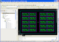
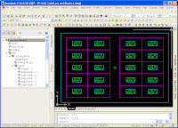
I’ve created an extremely simplified parcel layout consisting of two blocks, each with ten lots.

Now, the first thing we have to do is create two expressions. These expressions will strip off the portion of the parcel number we need for the label. The first expression I will call BLOCKLOT to BLOCK. This will convert the parcel number from the BBLL format to BB.

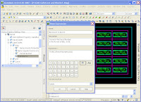
What this expression does is to take the parcel number, “BBLL” and divide it by 100. This results in “BB.LL”. It then Truncates this resulting value and we are left with “BB”. We can now use this expression anywhere we want to label just the Block number. Likewise, we can use an expression to convert the parcel number from the BBLL format to LL. I called this expression BLOCKLOT to LOT.

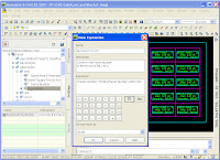
This expression is a little bit trickier but not too bad. In essence, we use the same expression as before to get the block number, “BB” but now, we multiply it by 100 to get “BB00”. We then subtract this from the original number to get just the lot number, “BBLL - BB00 = LL”.

Now that we have our two expressions, we can use them in a parcel area label style. I created a new label style and edited the text component. Since we have made these expressions, they are available to us to use in the text component.

This is what the final composition of the text component of our new label looks like:
Now that we have our label style all set up, we simply apply this style to the parcels we need labeled. The result looks like this:

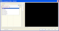
As you can see, we need to renumber our parcels to match our new labeling scheme. The block to the left is Block 1 and on the right is Block 2. In our Renumber/Rename Parcels dialog box, we set the starting number to 101, corresponding to Block 1, Lot 1.

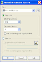
And then select our parcels in order. We then repeat the process for Block 2 using a starting number of 201 to correspond to Block 2, Lot 1.

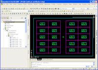
Our final product now looks very much how we would like to see it.

I hope you’ve enjoyed this issue of the Comm-Tech CAD Café.