Showing posts with label AutoCAD 2008. Show all posts

Friday, April 3, 2009

Another Way to Save Customizations

Hello again, I hope this note finds you all in a good mood. Here in Boulder it's a beautiful sunny morning, but we're supposed to get another snowstorm tonight that could continue into tomorrow. At least tomorrow there won't be as many people who have to get to work, so there won't be as many idiots - those who refuse to slow down! - sliding into the ditches.

I think you'll like this little tip. I have explained previously about saving your .cui file, and how that's where your custom settings live. Well, that wasn't wrong exactly, but I found out there's a better way, thanks to the Techs at Autodesk.
Have you ever noticed that when you install a new version of an Autodesk product, a message pops up telling you it noticed you have a previous version and would you like to migrate your custom settings?
I love how computers can be so polite.
What I found out was that you can use that function at any time, to save any custom settings you have. It's better and safer than depending on your acad.cui file to keep any custom toolbars safe. How this came about was a man called who had copied his .cui file from one computer to another and lost his custom toolbar names. They were still there, only it was hard to find them, and they were renamed "Toolbar 1","Toolbar 2", and so on.

So, here's another way to save your custom settings and avoid the problem this gentleman came up against.

In your Start menu ( sorry I don't know where to start in Vista, but if you've gotten proficient at using that OS I bet you'll be able to figure this out) go to All Programs, then find Autodesk, and then whichever version you customized. Notice the menu in the picture. From here you can both save your custom settings by exporting them, and you can import custom settings from previous versions.


You'll get this little warning, as shown on the right here. Notice that you can choose to save settings that 'live' on your network.


Doing this creates a .zip file, just pay attention to where you save it!


Then some day when you want to restore those settings, just reverse the process. Go to the Start menu as before, and in the Autodesk program you want to import to, select "Migrate Custom Settings". Browse to the zip file you created earlier, and it imports them.



At the end you get a report of what was installed and what doesn't work. I had a few error messages, mostly that access to the font files was denied, and then General Information and Migration Details.
This is a better way to have all your custom toolbars, icons, etc, safe and in a way that you can surely get them back again. The thing about this that I never thought of before is that you can use it to save and move custom settings from one machine to another, besides the normal function of using it to migrate custom things from one version to another.


Have a nice Spring day! I hope the weather is getting nice, wherever you happen to live. And for anyone who lives south of the equator - enjoy your Autumn. It's my favorite season.

Tuesday, March 24, 2009

Putting Annotative Objects to Work

Yesterday I did a review of how to create Annotative Styles, in Text, Dimensions and Multileaders. It's pretty obvious that these styles are worse than useless if you don't know how to use them, so let's get right into that.
You can put Annotative Dimensions, Text and Multileaders in your drawing either in Model space or Paper Space through a scaled viewport. The benefit of putting these objects in through a viewport that has already been scaled is that you are already sure what your viewport scale is going to be, so you don't have to wonder. Also, you won't forget to set the scale, which frequently happens when adding Annotative Objects while in Model space.
That being said, most people I talk to put their notes and dimensions on their drawing long before they get it set up to print, so we need to look at both ways of doing this.

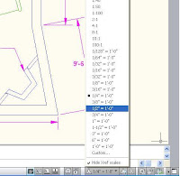
In Model Space, before you add notes or dimensions, choose the scale at which you want these objects to plot. In the lower-right corner of your screen, on the status bar, you can see the current scale. If you've never changed it, the default is 1:1. In the picture I've selected the flyout arrow, my current scale is 1/4"-1'-0", and I'm about to change it.


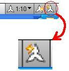
Notice the little button to the right of the Annotation Scale button. It is the Annotation Visibility button, and it controls whether you can see every Annotative object (ON) or only the ones that have the current scale (OFF). When you click this button, the light bulb changes from lit up (on), to dark grey (off), and on your command line you'll see
Command: ANNOALLVISIBLE
Enter new value for ANNOALLVISIBLE <0>: 1

If you prefer, you can type that command in, so then you need to know that 1=On, 0=Off
Take a look at these pictures, and notice how in the one with the light bulb icon 'on', you can see dimensions and notes of different sizes, but when the light goes dim, you can only see Annotative objects that have the current scale assigned to them:


In this next picture, notice how it looks when I leave the light bulb off and change the current scale in the list.


All the Annotative items created at the scale of 1:10 no longer show, and the ones with the 1:20 scale assigned to them are now visibile.


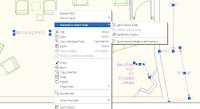
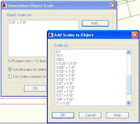
If you need certain Annotative objects to show in more than one scale, there are several ways you can make that happen. My first choice when I'm in Model space is to select the objects to which I want to add a scale, right click, and select either "Add current scale" - that's pretty self-explanatory - or select "Add/Delete Scales". You can add one or more scales to all the annotative objects you've selected.


As you can see from the picture above, they can be different types of objects and it still works. After you do this, these will all show up in any viewport that has that scale assigned to it. From this same menu, you can also delete any assigned scales. The Delete button is right below the Add button.


Another way to add scales to Annotative objects is with the ANNOAUTOSCALE command. It's the button in the picture - but be very careful with this button! If you have this on, as it looks in the picture, and you change the scale showing on the status bar, it will add the new scale to EVERY Annotative object you have! Everything, even if it's on a frozen or locked layer.


See the mess I made with this button! The Dimension layer was frozen, and the Notes layer (red) was locked. Thanks be that there is an "Undo" button!!


Another way to create Annotative text, dimensions or multi-leaders is to first set up your sheets, create the viewports you need, set their scales and lock them. Then on your layouts, double-click inside any viewport to put yourself in Model Space. When you put notes or dimensions in your drawing this way, they automatically are created at the proper scale.
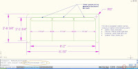
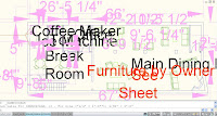
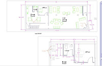
In this last picture, the Annotative text, dimensions and multileaders were put in through the viewports. You can really see the benefit of using Annotative text (I HOPE!) because even though these viewports are at different scales, the dimensions in each one print out at the same size, as do the room names. You may notice that the room names have two scales assigned to them, so they show up in both viewports. Nevertheless, I was able to adjust the position of each word so it fit in the room.


I truly hope this was helpful to someone out there who is trying to figure out how to work with Annotative Objects!

Monday, March 23, 2009

Annotative Objects Revisited

Since Annotative objects became part of AutoCAD in the 2008 version, there have been some changes, mostly simply in how it looks when you're using them. I'm going to go through the basics again of how to use annotative text, dimensions and leaders ( called Multileaders now ). In my humble opinion, this was the best thing to come out of the 2008 release. If you ever print out your project with viewports at different scales, you will be so happy if you learn how to use annotative objects! This is one problem everyone has been struggling with since day 1. (well, everyone who printed any part of their project at a different scale than the rest of it) But now - Problem Solved!
First of all- Annotative Text, Dimensions and Multi-leaders work best if you create an Annotative Style. Any style you already use can be made into an annotative style.

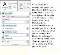
In 2009 AutoCAD, if you're using the ribbons, on the 2D workspace Home tab there is a panel named Annotation. If you click the flyout for that ( the black triangle) you'll be able to edit or create text, dimension and multileader styles. In the picture I highlighted where you would click on each of those, in blue. (You cannot highlight them all the way I showed here. I did some copy and paste to make it look that way).


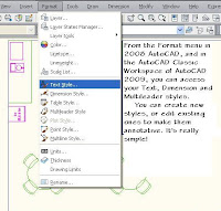
In 2008 or 'classic' AutoCAD, you get to the styles in the Format pulldown menu.


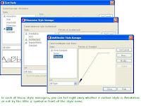
You can tell right away when you open any of the style managers whether a particular style is annotative or not.


To make an existing style annotative:

For Text styles, select the style you want to make Annotative. In the dialog box click on the box in front of the word "Annotative". Click "Apply".


For Dimension styles, choose the style you want to change, then select "Modify". Go to the 'Fit' tab, and check the "Annotative" box. Select "OK" to save the changes.


For Multileader styles, choose the style you want to change, then select "Modify". Go to the "Leader Structure" tab, and check the "Annotative" box. Select "OK" to save the changes.

When you're creating a new style, you'd do the exact same thing as above, at the time you are in the process of creating the style.

To create a new text style, in the style dialog box select 'New'. Give your new style a name, choose a font from the pulldown list, check the 'Annotative' box, and click "Apply".

To create a new dimension style, in the Dimension Style manager select 'New' and give it a name in the box that pops up. Go through the steps to choose how you want your dimension style to look, and when you get to the 'Fit' tab, choose "Annotative".

To create a new Multileader style, in the Multileader Style Manager, select 'New', then decide what kind of leader format you want, and whether you want it use Mtext or a block in the Content tab. Then in the 'Leader Structure' tab, be sure to check the box for "Annotative".

Now you've got it!

Not sure what do do with it?

Tune in tomorrow to find out how the Annotative Objects work. Same time! Same channel!

Monday, September 29, 2008

RegApp Cleanup Utitility

Hi again,
Have you ever gotten drawings from another company and they were enormous files for no discernible reason? Last week we had a client who was having strange problems with a whole lot of drawings. I enlisted the help of our Civil 3D instructor, Ken Martinez, and he showed me the difference between the typing in "purge" or "-purge" at the command line, as the only way to get rid of RegApps. You have a lot more control with "-purge".
Then just today, as a "Oh, by the way" comment today, Ken showed me this new Cleanup Utility on the Autodesk website, and I thought I ought to pass this along to you. I'm always looking for ways to eliminate headaches.

With this new Cleanup Utility, you can do a batch of drawings at once. Here's the link to the Autodesk page:
Excess Unreferenced RegApp IDs
RegApp Cleanup Utility

I did a little tiny bit of research, and found a good entry in the AUGI archives from 2006 that spells out better than I would how to use the purge command to get rid of invisible attached data from a drawing. It explains how it gets there and how to get rid of it. I copied the entry, (it's from 2006) and also credited the author. For cleaning up one or a few drawings, it's really easy.
From the AUGI website, in the Archives from 2006, is this tip on how to get rid of Xdata in a drawing. Written by Andy Manninen: (and I quote)

I would recommend to all AutoCAD users to run a -PURGE command, then select RegApps, * for all, and no to verify names. You may be surprised at what you will find... Regapps are added when you use certain software, and by implementing certain commands. If you purge these out you will find that your drawings will open much faster. I have not experienced any problems with purging the RegApps out because AutoCAD will generate these back as it needs them. With a clean drawing I have about 8 RegApps in my drawing. But I Have cleaned some that have around 157,000 RegApps. Cleaning that file, the size went from 3 MB to 400KB. The Main thing with RegApps in a drawing is that they act almost like a virus, if you xref in or insert an "infected" drawing, the RegApps propagate into the current drawing. That is why you need to make sure when you get files from an outside source you really should clean out the RegApps. The only way to clean these out without third party software is by using the "-PURGE" command on the command line, (not through PURGE) and you need to specify RegApps. (RegApps are NOT purged under the ALL).

Monday, March 17, 2008

Table Editing - Formulas

Just like in many other places, when Spring is heading to Colorado it often takes two steps forward and one step back. Yesterday was one of those steps back; sloppy, snowy, cold and beautiful. You can see the view out my window had a definite hint of winter to it. Today the wind is still blowing but the sun is out. A really nice day unless you're standing outside waiting for a bus.
But I digress - let's get back to Tables.
On the right is the table I worked with last time. Clicking on it selects the entire table, and hovering over it shows two symbols indicating the whole thing is linked and locked. That means the information in the table came from other objects, and it can't be manually edited without unlocking it.
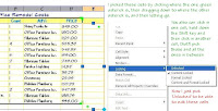
I want to add a column and a row for some total prices. One click in a cell, and then right-clicking, will let me add a column or row on the outside of the data extraction area. In this picture I've already clicked on a cell in the last row and added a row below it, now I'm clicking in the column on the right, and I'm adding a column. The next step - even though I added those cells and they're not part of the Data Extraction - I have to unlock them in order to edit them.


Next I put in a formula to multiply the cost times total number of blocks


Notice how many zeros are in the cell where I typed the formula? This gets me every time. So next I have to change the precision. If I change this before I copy the cells down, I won't have to change the precision any of the rest of the cells. Even though it looks like a normal field, editing this is different. If you double-click here you only have access to the formula.
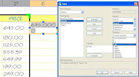
To change the precision of the result, you have to click once in the cell, right-click, choose Insert>Edit Field. I can hear you thinking to yourself, 'Insert? that doesn't make sense!' This is why I mention it. (For a normal field, like Save Date, you would double-click to get into the Text Editor, then click on the field itself, right-click and pick 'Edit Field').

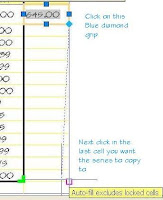
Once I have that done, it's as easy to copy the formula into other cells as three clicks - one in the cell you want to copy to select it, one in the blue diamond, and one in the last cell of the series you want to copy.


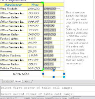
To get a total, I use the same steps as when I inserted the Equation, to insert a formula in a cell, except this time I pick SUM. I've illustrated how to choose the cells you want to the SUM field to add together; it's much easier than trying to explain. Even when I use small words so you'll be sure to understand. (Any of you familiar with that phrase?)
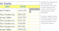
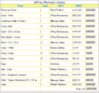
The last picture, the one on the right, is of my finished table. I'm happy with the way it looks, and since I used Attribute Extraction to make the table in the first place, I know I didn't forget to count anything. I love it.


P.S. This post was the third one I've done on Tables. If you always get to this blog from the link in the Comm-Tech emails, you might want to go back and read the other entries I posted about Tables. I can see that otherwise this could be a little confusing. - LuAnn

Tuesday, February 19, 2008

Custom Table Style

I used to spend a lot of time creating symbols schedules, light fixture schedules, equipment schedules - anything they could think of that needed to be put in neat rows and columns. Invariably after I was finished and it looked just right, (those of you who did this know it could really be a lot of fiddly picky work!), something would either get eliminated or added, and inevitably that Thing would be in the middle of my nice neat schedule. So I'd have to move a bunch of stuff down, and copy the row, and of course the new Thing would have some long name that wouldn't fit in the same size box as all the other Things, and I'd have to adjust the whole blasted schedule.
I wish AutoCAD Tables had been around back then! It would have saved me so much pain!
But they're here now, they've been out since 2005 and every year they've improved them. With the new features added to Tables in 2008, there really are no more excuses, you ought to be using them. Of course, it's not so fun if you don't know how to use them, or how to make them look the way you want. So let's look at some basics of table styles today, and next time we'll look at more of their features. By the time we're finished, you're going to want to make tables for everything!
First of all, the AutoCAD templates come with a Standard Table Style, with Standard text, sized by default to be put in paper space. They figure you'll only want these on one sheet, so you'll create them on that sheet, at the size you want it to print. Makes sense, so let's stick with that for our first table style.
Let's say that a drawing has the blocks you use and you were told to make a simple schedule from the furniture blocks. All they want is a picture of it, with the name next to it. They want a border around the whole thing, and a title above it, but they don't want any lines between the blocks.
Get to the Table Style dialog box either from the Format Pulldown Menu, or from the Styles Toolbar - it's the Table with the paintbrush over it. Click the New button to create a new style, and give it a name. This puts you right into the new table style so you can edit it.
There is a pulldown at the top where you choose which Cell Style you're editing. For each Cell Style, you click on each of the 3 tabs - General, Text, & Border. Click through the pictures below to see how to create a new Table Style.


When you're inserting a table, you can choose how many columns and rows it has, or if you choose window, the column and row amount will be decided by where you click. You can easily add or delete rows or columns later.


To add a block to a cell, choose it with one click, then right-click. If you double-click you'll be in the text editor.


Then it's just like inserting a block in your drawing, except you have an Auto-fit box to make the block fit in the cell, and an alignment pulldown so the block sits where you want it to in the cell.
I added blocks and text to my table - on the right is a picture of how it looks in Paper space, and in a print preview.

Next time - soon, I promise - I'll go into some of the new, cool features of Tables they added in AutoCAD 2008. Talk to you soon!

Monday, September 17, 2007

New Dimension Tricks

We are completely moved into our newly remodeled office building. (I'm posting a bunch of pictures in my next blog.) After so much chaos and disruption I am very happy to get back to a normal work day! If you click on the link you can see our new digs. I now have a window looking out over trees and things! Who wouldn't love that?

Today I'm going to show you a couple new features that have been added to Dimensioning.
Here's a picture of the two I'm writing about, shown on the pulldown menu, Dimension Space & Dimension Break. Of course these are on the Dashboard and the Dimension Toolbar, I just like the fact that you can see the icon and the command name at the same time on the pulldowns.


This first tip is a little different take on the Dimension Space (DIMSPACE) command.

When you have a line of dimensions that maybe should have been created with "DIMCONTINUE" - as you see on the right here - with Dimension Space you can easily fix 'em up. After starting the command, choose the dimension you want all the others to line up with. The one I chose is highlighted there (on the right)

Then use a crossing window to pick all the ones you want to line up with it, and use Zero as the spacing.


All the dimensions will line up with the one you chose as a reference. Sweeeet.


This command is most often used when you have a whole bunch of dimensions stacked too closely, or just so unevenly that they don't look professional.
The steps are the same - start the command, pick the reference dimension, and then use a crossing to pick the rest of the dimensions you need to line up properly.


Then enter the spacing distance in drawing units. In this case the spacing chosen was 15. Looks a lot better, doesn't it?


Remember, if the number you chose just doesn't look right, there's always Undo!


The last thing I want to show you today is the Dimension Break command.

When you have dimensions that overlap you don't have to use a Wipeout anymore. You can set any dimension to break where it overlaps another one by using the DIMBREAK command. It's really easy to use.

Start the command, either select the object you want to break, or M for Multiple and then select several dimensions using a crossing.

Then you have to hit Enter to accept the 'Break' option, and that's IT.


Nicest of all, when you grip edit the location of a dimension that has had DIMBREAK applied to it, the break moves with it.

Give this a try! I'll be writing again soon, so have fun drawing and I'll see you here next time.

Wednesday, August 22, 2007

Customize the Dashboard

Hi again! This time let's look at how to customize the Dashboard.

I know it's hard to change the way you've always accessed your commands, so I thought perhaps if you knew you could customize the Dashboard to look the way you want it, you all might just give it a try.
First of all, so we're all on the same page - the Dashboard was there in AutoCAD 2007, but only in the 3D Workspace.
Now in 2008 they've added it to the Workspace named '2D Drafting and Annotation'. They've also added a lot of functionality; you can customize your Dashboard now like you could the toolbars, and since they hide themselves when you don't need them, you can maximize your drawing space. (I mean it doesn't have to be all filled up with toolbars any more.)

Each of those rows with the faint grey line underneath is a control panel. You can control which control panels show. Right click on any control panel, you'll see the list of available panels. Only the ones that are checked will show. So, the first way you can customize the user interface is by choosing which control panels you would use. Once you have that set up, go to the Workspace Toolbar ( or the Tools menu; Tools>Workspaces ) and save as a new name. Next time you want just those Control Panels, choose that Workspace from your list and voila, you've got it. ("Tish, you spoke French!")

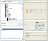
The fun part is making your own control panels. You can right click on any of the panels (not anywhere else on the Dashboard) and select "Customize". It'll put you into a folded-up display of the CUI dialog box. ( Customize User Interface). In the illustration here I've labeled where you click to open up the dialog box.

To open up the list of exising Dashboard panels, in the top left section of the CUI dilaog box, where it says "Customization in all CUI files" click the "+" in front of "Dashboard Panels". Right click exactly on those words and one of your choices will be "New". I selected that, in this picture you'll see my new panel.
One way to add commands to my panel is to find them from the list on the bottom there, and just drag them one at a time onto the Control Panel. If I wanted to, for example, I could drag every different Arc command onto one Control Panel and have them all at my fingertips.

By right-clicking on your Control Panel, you can add another row, a separator or a flyout; duplicate an object, or remove it.
Another, faster way to make Control Panels is to drag an entire toolbar onto a Control Panel. Up in the top section, find a toolbar that has most of the commands you want, and just drag and drop it onto your Control Panel. You need to drag it right onto the name , it will make a flyout on the row if you drag it there. The tool palette turns into a row on your Panel


Now on the right side of this dialog box you can see a preview of your new Control Panel. Notice the toolbar you dragged down formed a row, and the original row is now moved and became the 2nd row. By right-clicking on it, you can delete the other row if you don't need it.

Also, by right-clicking on individual buttons, you can delete any you don't want.
The fun part is adding new commands to these. Any command that you can find in the bottom left section of the CUI box can be dragged onto any dashboard. In the next illustration, I dragged a command from Express Tools that doesn't have an icon assigned to it. Notice the question mark for a button.
Also notice in the lower right corner, all the icons used for Toolbars and menus are showing there. It's not hard to customize one of those to make your own icon.


Scroll through the icons until you find one that's close to what you would like for your command. For the following example, I dragged the command for snapping Midway between two points onto my toolbar, so I started with the icon for Osnap-midpoint. In the picture below you can see it in the background, I clicked on Edit and then changed the bitmap as you see here. Then I just pick the "saveas" button, and AutoCAD puts me into one of those deeply buried folders, named Icon. Use that to store your custom icons.


Once you've saved it, the icon shows in your list, so all you have to do is scroll down to the bottom of the list and select it. Then it'll show up on your Control Panel.
By the way, if you don't use the botton now, it won't show up here later easily. It's best to do these one at a time.


Here is another custom button I made, for the Express Tools command "Replace block with another block". In this illustraton you can see the path where my custom icons are saved by default. Using this default location makes it easy for you to transfer these next time you upgrade the software.


Last of all, if you want to assign an image to the Control Panel itself, it's as easy as pie. Click on the title of your dashboard, scroll through the icons and click one. It'll then be assigned to the edge of your control panel. You don't have to do that of course. I made a custom one, and perhaps I shouldn't have used red, since all the other icons are just shades of blue. What can I say ? - I like a lot of color!